As global solar deployment accelerates, roof-mounted systems face a practical question: Why use ballasted mounts instead of roof penetrations? The answer involves waterproofing, structural capacity, wind behavior, maintenance, and project life. The IEA Photovoltaic Power Systems Programme reported that global photovoltaic capacity exceeded 1.6 terawatts by the end of 2023. More panels now sit above warehouses, factories, and commercial buildings. Small installation decisions can create large long-term consequences.
Ballasted mounts hold arrays with engineered weights, rather than bolts passing through the roofing membrane. That can reduce puncture points, flashing work, and leak-related service calls. The National Roofing Contractors Association treats the roof as a complete assembly, not merely a surface. Roofing expert Reid Ribble states, “The roof is a system, not just a surface.” His warning matters when installers place steel, mats, and cables above aging membranes.
Industry reports also show why caution is necessary. The U.S. Department of Energy’s Better Buildings guidance emphasizes roof condition, structural review, and coordinated maintenance before solar installation. Ballast is not automatically safer. Added dead load may exceed a roof’s reserve capacity. Wind uplift can shift poorly designed arrays. Drainage paths can become blocked.
That detail is easy to miss.
A credible design therefore begins with drawings, load calculations, wind-zone analysis, and a roof warranty review. It should also allow technicians to reach drains and equipment without dragging panels across the membrane. Ballasted systems can reduce penetrations, but they do not remove engineering responsibility. Sometimes, penetrating attachments remain the better choice. The honest answer depends on the building, climate, roof age, and local design requirements.
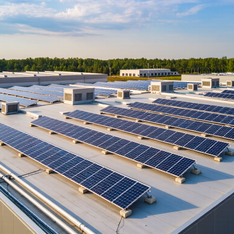
Ballasted solar mounts hold panels in place with carefully calculated weight rather than bolts driven through the roof. A typical assembly uses support trays, concrete blocks, and rows of tilted modules. Wind can push upward or sideways, so engineers model roof height, edge zones, panel angle, and local exposure. The ballast must resist movement without exceeding the roof’s load capacity. It is not simply “add more blocks.” Too much weight can be a problem.
Installers usually place protective pads beneath trays to limit abrasion and help protect the roof membrane. Modules are arranged in connected rows, with gaps for drainage and maintenance access. The design may also use aerodynamic deflectors to reduce wind forces, though their effect depends on the layout and site conditions. A structural review should check existing roof loads, including equipment, snow, and water. Small details matter. Drainage paths can be easy to overlook.
The market context is substantial: IRENA’s Renewable Capacity Statistics 2024 reports that solar power added about 346 GW worldwide in 2023. That figure does not mean every roof suits a ballasted system. A roof’s age, construction, and allowable load still decide feasibility. Ballasted designs can avoid many roof penetrations, but they are not penetration-free in every project; attachments may be needed where wind loads demand them. That distinction deserves a careful site-specific review.
Ballasted mounts hold solar panels in place with carefully arranged weight rather than screws driven through the roof. Metal trays or rails support the panels, while concrete blocks or other approved ballast resist wind uplift. The roof membrane stays intact. That matters because every penetration can create a potential path for water, especially around aging seals or poorly detailed flashing.
The system’s stability depends on more than adding weight. Installers need to check roof capacity, panel layout, wind exposure, and the building’s structural drawings. They may use wind-tunnel data or project-specific engineering to determine ballast locations and quantities. A flat roof with clear access is often easier to assess. Still, ballast adds a real load, and not every roof can carry it safely. That part is easy to underestimate.
During installation, crews should protect the roof surface with compatible pads and keep drainage paths clear. A block placed over a drain can cause trouble later. Inspections should check for shifted ballast, damaged pads, and loose connections after severe weather. Ballasted mounts avoid roof penetrations, but they do not remove the need for careful design. Sometimes the simplest-looking layout needs more engineering than expected.
A roof is more than a surface for solar equipment. It is a layered system of membranes, insulation, and drainage paths.
With a ballasted mount, carefully calculated weight holds the array in place without fastening supports through the roof. No new holes. That can reduce the chance of water entering around mounting points, especially where older sealants might otherwise crack or loosen over time.
Avoiding penetrations also helps preserve the roof membrane’s continuity. Installers can position protective pads beneath supports and keep equipment clear of drains, seams, and access routes. These details matter: a blocked drain after heavy rain can cause trouble even when the roof has no new holes. Ballast must be sized for the building and local wind conditions, and the roof must be checked for its ability to carry the added load. A qualified structural review is essential.
There are trade-offs. Ballasted systems can add substantial weight, and not every roof can support them. Protective pads may shift or wear, so inspections still matter. I have seen plans that looked tidy on paper but left too little room for maintenance. That is easy to miss. A careful site assessment, clear drainage paths, and periodic checks help protect both the rooftop and the system above it.
China Top 10 Ballasted Mounts: Why Avoid Roof Penetrations?
Evaluating ballasted mounts in China starts with the roof, not the rack. Check the roof’s load capacity, surface condition, drainage paths, and insulation before comparing designs. A system that avoids drilling can reduce leak risks, but added ballast still places weight on the structure. This trade-off is easy to underestimate.
Local conditions matter. Coastal sites may need careful corrosion checks, while open rooftops can face strong wind uplift. Ask for project-specific wind calculations, verified component specifications, and a clear ballast layout. Confirm that pads will not block drains or damage the waterproofing layer. Installation teams should also inspect the roof in person; drawings rarely show every uneven seam or aging patch. Some details may still be missed.
Tips: Request structural review before ordering. Compare the total installed load, not only the mounting hardware. Keep access routes clear, and record the roof condition before and after installation. If the roof has limited capacity, a ballasted option may not be the safer choice.
A practical comparison of key evaluation factors for non-penetrating photovoltaic mounting systems on suitable flat roofs. Actual design suitability and ballast requirements must be verified for each project.
| No. | Evaluation factor | Why it matters | What to verify | Practical assessment |
|---|---|---|---|---|
| 1 | Roof penetrations | Avoiding anchors through the roof membrane can reduce the number of new potential water-entry points. | Confirm the system is genuinely non-penetrating and does not require concealed mechanical anchors. | Useful where preserving an intact waterproofing layer is a priority; not a guarantee against all leaks. |
| 2 | Structural capacity and ballast load | Ballast adds permanent load, while wind actions and other roof loads also affect structural demand. | Obtain a project-specific structural review using verified roof construction, existing loads, and system reactions. | A key go/no-go factor; do not assume a roof can support a ballasted array based on roof area alone. |
| 3 | Wind exposure and uplift | Wind pressure and suction vary with location, building height, roof zones, edge conditions, and array layout. | Check project wind design inputs, corner and perimeter zones, array geometry, and the calculated restraint strategy. | Do not use a single ballast value for all sites; China projects require location- and building-specific assessment. |
| 4 | Roof membrane compatibility | Support feet and load-spreading pads can interact with waterproofing materials and roof finishes. | Check material compatibility, contact pressure, drainage paths, and any membrane-provider requirements. | Use suitable protective interfaces and avoid details that trap water or damage the roof surface. |
| 5 | Roof slope and drainage | Slope affects system stability, while obstructed drains or ponding can increase roof-maintenance risks. | Confirm allowable roof slope and preserve drainage routes, outlets, and access for inspection. | Best suited to roofs within the mounting-system design limits and with a functioning drainage plan. |
| 6 | Roof condition and remaining service life | An array can make later roof repairs more difficult, even when the mounting system does not penetrate the roof. | Inspect the waterproofing layer and roof structure; compare expected roof and PV system service periods. | Repair or renew a roof where necessary before installation, and plan for access and future maintenance. |
| 7 | Seismic and sliding stability | Seismic actions, friction, roof surface characteristics, and array connections can affect system stability. | Review applicable local seismic design requirements and verify sliding, overturning, and connection behavior. | A ballasted layout should not be assumed suitable without project-specific engineering checks. |
| 8 | Installation and roof access | Modules, frames, and ballast must be moved and installed without overloading or damaging the roof. | Plan delivery routes, lifting, temporary material storage, worker access, and safe work procedures. | Installation logistics depend on the building layout and should be included in the construction plan. |
| 9 | Maintenance, fire access, and roof equipment | PV arrays must not prevent access to drains, rooftop equipment, inspection routes, or required safety provisions. | Coordinate the layout with building operations, applicable fire and safety requirements, and maintenance access needs. | Reserve access paths and keep critical roof features reachable throughout the system’s service life. |
| 10 | Design documentation and verification | Reliable decisions require traceable assumptions, calculations, drawings, and installation checks. | Request project-specific structural and wind calculations, layout drawings, material details, and inspection records. | Have qualified professionals verify applicable Chinese and local requirements for the project location. |
Note: Ballasted mounting is not automatically suitable for every flat roof. Final selection requires site-specific review of structural capacity, wind and seismic actions, roof condition, waterproofing, drainage, and applicable local requirements.
China’s rooftop solar market is expanding quickly. The National Energy Administration reported 216.88 GW of new solar capacity in 2023, including distributed projects. That scale makes roof compatibility more than a detail. It is a design constraint.
Ten ballasted options suit different roofs: south-facing fixed-tilt, east-west low-tilt, shallow-angle, elevated-tilt, portrait-module, landscape-module, continuous-tray, discrete-block, hybrid ballast-and-anchor, and green-roof-compatible systems. Low-tilt east-west layouts can fit more modules in limited space, but row spacing and drainage still matter. Discrete blocks allow flexible placement; continuous trays can spread contact loads. Neither removes the need to check roof capacity. No drilling helps, but wind uplift remains.
Compare each option by roof load, wind exposure, drainage, access, and installation effort. The IEA PVPS report Trends in Photovoltaic Applications 2024 documents China’s exceptional solar deployment, but national growth figures cannot determine whether a specific roof is suitable. A structural engineer should review the roof’s dead-load allowance and local wind conditions before selection. Small details count. A blocked drain or uneven ballast pad can undermine an otherwise tidy layout. Sources: China National Energy Administration, 2023 national power industry statistics; IEA PVPS, Trends in Photovoltaic Applications 2024.
It holds solar panels in place using weighted trays and blocks instead of relying mainly on roof bolts. The roof still needs careful review.
Their calculated weight resists wind pushing panels upward or sideways. Adding more blocks is not automatically safer.
No. Roof age, construction, and allowable load affect suitability. Existing equipment, snow, and standing water also count.
Not always. Some projects need attachments where wind loads require them.
Options include low-tilt east-west, fixed-tilt, portrait-module, landscape-module, and green-roof-compatible layouts. The best fit depends on the roof.
Gaps help water flow and leave room for maintenance. A blocked drain can create trouble.
Pads beneath trays help limit abrasion to the roof membrane. Continuous trays can spread contact loads; discrete blocks allow flexible placement.
Review roof capacity, wind exposure, drainage, access, and installation effort. A structural engineer should assess the specific site. Small details matter.
This article explains what ballasted solar mounts are and how they support panels using carefully arranged weights rather than fasteners driven through the roof. It describes how the mounting system keeps panels in position while distributing their load across the rooftop, and examines why avoiding roof penetrations can help reduce the risk of leaks, protect roofing materials, and simplify installation or future maintenance. The central question, “Why use ballasted mounts instead of roof penetrations?” is considered in terms of rooftop protection and practical project requirements.
The article also outlines key factors for evaluating ballasted mounts in China, including roof type and condition, structural load capacity, wind exposure, system layout, component quality, and installation needs. It concludes with a comparison of ten ballasted mount options, showing how their designs and performance considerations may suit different rooftops and project conditions.

Trope Solar