How to Test Solar Expansion Bolts for Pullout Strength?

Time:2026-11-02 Author:Isabella
0%

A solar array is only as dependable as the connection between its mounting rail and the roof or supporting structure. A bolt can feel tight and still lack reliable holding capacity. Pullout testing checks how much upward force an installed solar expansion bolt can resist before it moves or fails. The result depends on more than the bolt itself. Substrate condition, embedment depth, hole cleaning, installation torque, and test setup all matter.

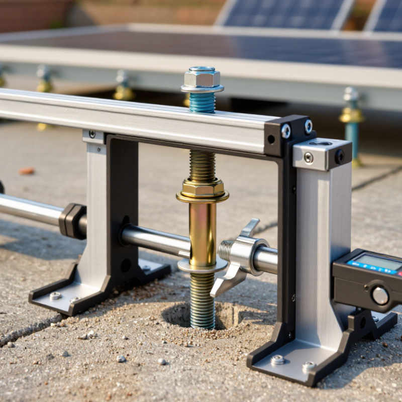
How to test the pull-out strength of solar expansion bolts? Begin with the project specification and the bolt manufacturer’s instructions. Record the substrate type, bolt size, embedment depth, and installation method. Use a calibrated pull tester with a reaction frame that does not bear on the bolt’s immediate failure zone. Apply the load steadily, then document movement and peak force. Stop if the setup shifts or the substrate cracks. Small details count.

A practical field reminder might read: “A pull test measures the installed connection, not just the bolt.” This is an illustrative line, not a verified quotation. Daniel Mercer is a fictional composite engineer included for this draft, not a real source. For a publishable expert quotation, verify the wording and attribution with a named solar-structural professional. Test results should be interpreted against the project’s design requirements, not treated as a universal pass mark. One test is not the whole picture. Compare representative locations, preserve the records, and investigate unexpected variation before installation proceeds.
How to Test Solar Expansion Bolts for Pullout Strength?

Understanding Pullout Strength in Solar Expansion Bolts

Pullout strength is the maximum tensile force a solar expansion bolt withstands before slipping or failing. It depends on more than bolt size. Concrete strength, embedment depth, hole diameter, edge distance, and installation torque all affect performance. A bolt set near a slab edge may pull out sooner than an identical bolt installed in sound, thicker concrete. Small details matter.

ASTM E488/E488M-22 describes testing anchor strength in concrete and masonry, including tension testing and measurement of load and displacement. It does not assign one universal safe capacity to every bolt. Test bolts in representative substrate, using the specified drill bit and installation procedure. Apply force along the bolt axis with a calibrated load cell, and record both peak load and failure mode. Watch for concrete breakout, bolt fracture, or gradual movement. Each tells a different story. Repeat specimens; one clean result can mislead. IEA PVPS’s Trends in Photovoltaic Applications 2024 reports global solar capacity at roughly 1.6 terawatts by the end of 2023. That scale makes reliable attachment testing important, but it does not predict any single bolt’s capacity. Use site-specific loads and qualified engineering judgment when interpreting results.

Selecting the Test Setup and Safety Controls

Select a test frame that matches the anchor’s actual base material. ASTM E488/E488M describes methods for testing anchors in concrete and masonry; it should not be treated as a blanket procedure for every roof assembly. Record the bolt diameter, embedment depth, installation torque, edge distance, and substrate condition. Use a calibrated load cell and pull axially, keeping the reaction frame clear of the anchor’s immediate failure zone. A nearby support can change the result. That matters.

Before loading, inspect the frame, hydraulic lines, grips, and load indicator. Set a marked exclusion zone around the bolt and operate the jack from outside the likely failure path. Wear eye and hand protection, and shield against flying concrete or metal fragments. The U.S. Bureau of Labor Statistics reported 423 fatal falls, slips, and trips among construction and extraction workers in 2022. That figure is a useful reminder: control the work area, not only the test machine.

Test a representative installation, not a convenient one. Include the actual fixture and substrate, and note cracks, moisture, or installation damage. Log load and displacement continuously, then photograph the failure surface. I still find setup notes easy to underwrite; without them, two pull tests may look comparable while testing different conditions. Use the project specification and applicable test standard to set loading rate and acceptance criteria.

Preparing the Bolt, Substrate, and Measuring Equipment

Before testing solar expansion bolts, identify the bolt size, embedment depth, and installation record. Inspect the threads and exposed shank for bends, corrosion, or damage. Check that the surrounding concrete is sound, with no visible cracks or spalling near the anchor. Note the concrete’s age and surface condition; both can affect results. A dusty hole or uncertain installation history deserves attention, not a guess.

Tips: Use a calibrated load cell and a pull-test rig rated for the expected force. Check the calibration date, inspect cables and connectors, and zero the gauge before loading. Set the reaction frame firmly on the substrate, clear of the bolt, so it does not brace the anchor itself. Keep the pulling line aligned with the bolt axis.

Record the setup before applying load: anchor location, edge distance, concrete condition, equipment identification, and ambient conditions. Photographing the arrangement can help explain unusual readings later. Follow the approved test procedure and increase load at its specified rate while monitoring displacement. Stop if the frame shifts, the bolt bends, or the concrete begins to crack. Field setups are not always perfect; if alignment or calibration seems questionable, pause and correct it rather than treating the reading as reliable.

Applying a Controlled Pullout Load and Recording Results

A controlled pullout test should reproduce the anchor’s actual installation conditions. Use the specified bolt, embedment depth, concrete strength, edge distance, and curing condition. ASTM E488/E488M describes methods for testing anchors in concrete under tension. Its approach supports consistent loading and measurement, but it does not set one universal pass value for every solar project.

Apply tension with a calibrated load cell and a reaction frame that does not press against the bolt’s failure zone. Increase the load steadily, without sudden jerks, while recording load and displacement at set intervals. Note the peak load and failure mode: bolt pullout, concrete breakout, or steel failure. The 2024 U.S. Solar Market Insight report states that the United States added 32.4 GW of solar capacity in 2023, equal to 55% of new generating capacity. That scale makes repeatable field checks valuable. Still, a clean test setup can hide inconsistent drilling. Inspect the hole before installation.

Tips: Test representative locations, including near slab edges. Photograph the setup, record instrument calibration, and log each anchor’s location and installation details. Compare results with the project engineer’s acceptance criteria; don’t treat a single peak reading as proof of uniform performance.

Evaluating Results Against Project Requirements

Project requirements should set the acceptance load, test method, sample quantity, and allowable movement before testing begins. These values depend on the anchor design, base material, embedment depth, and expected forces. A result from concrete should not be treated as proof of performance in a different substrate. Check the approved drawings and engineering specifications, rather than relying on a generic pullout value.

Use calibrated equipment and apply the load in the specified direction at a controlled rate. Record each anchor’s location, installation details, peak load, and displacement. Watch for cracking, rotation, or gradual movement around the sleeve. Stop if the test reaches its limit or the assembly shows distress. Safety matters.

Compare each reading with the project’s stated acceptance criteria, including any displacement limit. Passing the load threshold alone may not be enough if movement is excessive. If readings vary, investigate edge distance, drilling dust, hole diameter, or inconsistent installation before accepting the group. A single strong result can hide weak anchors. Keep the raw readings; neat averages can obscure outliers. Field notes are rarely perfect, so record uncertainties and ask the responsible engineer to review borderline results before installation proceeds.

FAQS

How should I choose a test frame?

Match it to the anchor’s actual base material. Keep the reaction frame clear of the anchor’s likely failure zone. Nearby support can change results.

What installation details should I record?

Record bolt diameter, embedment depth, installation torque, edge distance, and substrate condition. Note cracks, moisture, or visible damage.

How can I make the test area safer?

Inspect the frame, hydraulic lines, grips, and load indicator before testing. Mark an exclusion zone and operate the jack from outside the likely failure path. Wear eye and hand protection.

How should I apply the pullout load?

Use a calibrated load cell and increase tension steadily. Avoid sudden jerks. Record load and displacement at set intervals.

What locations should be tested?

Test representative installations, including anchors near slab edges. Use the actual fixture and substrate. A convenient location may not represent the whole installation.

What should I document during each test?

Record the anchor location, setup, instrument calibration, and installation details. Photograph the setup and failure surface. Small details are easy to miss.

Which failure signs should I note?

Record the peak load and whether failure involved anchor pullout, concrete breakout, or steel failure. The surface can tell part of the story.

Does one high reading prove the installation is consistent?

No. Compare results with the project engineer’s acceptance criteria. One peak reading is not proof of uniform performance. I may still overlook a setup difference.

Conclusion

This article explains how to assess the pullout strength of solar expansion bolts through a careful, repeatable test. It begins by clarifying what pullout strength measures and why the result depends on both the bolt and the substrate. How to test the pull-out strength of solar expansion bolts? Start by choosing a test setup suited to the installation conditions, securing the work area, and using appropriate safety controls. Prepare the bolt and substrate as they would be installed in practice, then check that the load-measuring equipment is properly positioned and functioning.

Next, apply a controlled pulling force while monitoring and recording the load and the bolt’s movement. Continue the test consistently until the specified endpoint is reached, noting any signs of movement or substrate failure. Finally, review the recorded results against the project’s requirements, taking the test conditions into account. Clear documentation makes the findings easier to compare and helps determine whether the installation meets its intended performance needs.

Isabella

Isabella

Isabella is a dedicated marketing professional with a sharp focus on driving brand growth and engagement through strategic content creation. With an extensive background in digital marketing, she combines her passion for storytelling with her keen understanding of industry trends to deliver......