China Top 10 Solar Grounding Suppliers How to Ground Arrays?

Time:2026-09-19 Author:Oliver
0%

Solar grounding is a small system detail with serious safety consequences. The IRENA Renewable Capacity Statistics 2024 report recorded 1,419 GW of global installed solar capacity by the end of 2023. More arrays mean more grounding connections, exposed metal, and inspection points. Poor bonding can create dangerous touch voltages, especially during insulation faults or lightning events. This makes supplier selection more important than a simple price comparison.

This guide examines China’s top 10 solar grounding suppliers and the products behind their market reputation. The assessment considers grounding clips, copper and aluminum conductors, lugs, clamps, earthing electrodes, corrosion resistance, test documentation, and production traceability. IEC 62548 provides design guidance for photovoltaic arrays, while UL 2703 addresses mounting systems and bonding performance in relevant markets. These standards do not replace local electrical rules. They also do not guarantee a product will suit every roof, soil condition, or mounting rail.

How to ground a solar array properly? Begin with a documented bonding path from module frames to the mounting structure, grounding conductor, and earth termination. Check continuity with calibrated equipment, not only visual inspection. Pay close attention to anodized aluminum surfaces, stainless-steel fasteners, buried joints, and coastal salt exposure. The NREL report Best Practices for Operation and Maintenance of Photovoltaic and Energy Storage Systems emphasizes planned inspections and electrical testing. That practical point is often underestimated.

A supplier may appear excellent on paper. Field evidence can tell a different story. Product certificates, batch records, installation guidance, and technical support deserve equal attention. This ranking should therefore be treated as a purchasing reference, not an absolute verdict. Solar projects differ. Grounding design must be reviewed by qualified professionals before installation.
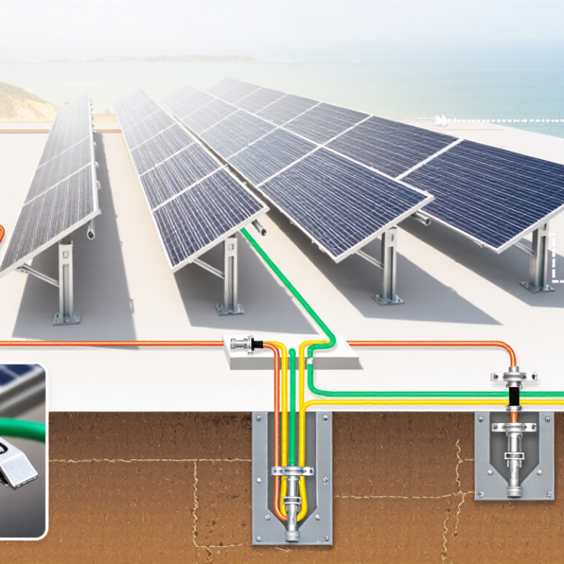
China Top 10 Solar Grounding Suppliers How to Ground Arrays?

China’s Top 10 Solar Grounding Suppliers: Selection Criteria and Market Scope

China’s top 10 solar grounding suppliers should be assessed through evidence, not advertising claims. A credible selection considers grounding lugs, clips, copper conductors, earth rods, and complete array solutions. Suppliers need documented electrical testing, material certificates, factory traceability, and consistent production records. Experience with rooftop, ground-mounted, and floating solar projects also matters. Different sites create different risks.

Market scope extends beyond domestic installations. Leading suppliers often serve utility-scale farms, commercial rooftops, agricultural projects, and international EPC contractors. Their products should suit dry deserts, humid coastlines, freezing regions, and high-corrosion soil.

Check conductor compatibility carefully. Copper touching aluminum without proper separation may accelerate galvanic corrosion. Small details matter.

During supplier evaluation, request sample assemblies and inspect the connection by hand. A reliable grounding clip should fit firmly, resist movement, and maintain contact after thermal expansion. Ask for test reports from recognized laboratories and clear installation instructions. Export experience is useful, but it does not replace technical proof. A supplier may have excellent machinery and weak field support. That is easy to miss.

No checklist is perfect. A factory visit can reveal storage problems, rushed inspections, or unclear batch labeling. Speaking with installers may expose issues that brochures hide. Pricing also deserves caution. The cheapest grounding component may increase replacement work, especially where salt, dust, or repeated maintenance affect connections. Selection should balance verified performance, delivery capacity, engineering support, and long-term site reliability.

Solar Array Grounding Basics: Purpose, Components, and Safety Principles

Solar Array Grounding Basics: Purpose, Components, and Safety Principles

A solar array needs grounding to control fault current and reduce shock risk. It also helps protect equipment during insulation failures and lightning events. The grounding path usually includes module frames, mounting rails, bonding hardware, conductors, and an approved grounding electrode system. Every metal part that could become energized should connect through a reliable, low-resistance path. Grounding is not the same as bonding. Bonding joins conductive parts, while grounding connects the system to earth. That distinction is often overlooked.

Tips: Use listed grounding clips or lugs designed for the mounting material. Remove coatings only where instructions permit. Tighten connections to the specified torque. Loose hardware can create heat, noise, and intermittent faults. Inspect exposed conductors for cuts, corrosion, and sharp bends. A qualified electrician should verify continuity and follow local electrical requirements. Do not assume a visible wire proves a safe connection.

Field experience shows that rooftop arrays often fail at small details. Water can collect beneath poorly positioned hardware. Dissimilar metals may corrode quietly. A rushed inspection may miss both problems. Test before energizing, then document the results and retest after major changes. Grounding design should match the inverter, array layout, structure, and site conditions. Requirements vary by jurisdiction, so generic online diagrams cannot replace professional review. Even experienced installers should question unclear drawings and check every connection.

How to Design a Reliable Grounding System for Solar Arrays

Designing a reliable grounding system for solar arrays begins with the site, not the hardware. The IEA PVPS Trends 2024 report recorded about 447 GW of new solar capacity in 2023. That scale makes grounding discipline essential. Measure soil resistivity before choosing electrodes. Map array rows, inverter locations, cable routes, and nearby lightning paths. A clean drawing helps.

Bond module frames, mounting structures, combiner boxes, and inverter enclosures into a continuous equipotential network. Follow IEC 62548 and the locally adopted electrical code. Use listed conductors, protected joints, and compatible metals to reduce corrosion. Keep grounding paths short, visible, and mechanically secure. Do not assume anodized aluminum creates a dependable electrical connection.

Test it properly. Check continuity across every bonded section, then verify earth resistance using a documented method suited to the site. Record moisture, temperature, test equipment, and measured values. NFPA 70 requires grounding and bonding methods that protect people and equipment, but local rules may demand more. A single resistance number cannot prove system quality.

Details matter. Buried copper can corrode beside galvanized steel. Loose washers can interrupt a bond after years of thermal cycling. NREL field-performance research has repeatedly linked maintenance and environmental exposure with long-term PV reliability concerns. The design may look complete. It may still need review. Recheck connections after installation, severe weather, and major maintenance.

China Top 10 Solar Grounding Suppliers How to Ground Arrays? - How to Design a Reliable Grounding System for Solar Arrays
No. Design Dimension Recommended Practice for Solar Arrays Relevant Standard or Basis Key Verification Point
1 Grounding Architecture Use a coordinated system consisting of equipment bonding, an equipment grounding conductor, an array grounding network, and the site grounding electrode system. Bond exposed conductive parts so that a fault has a low-impedance return path. IEC 60364-7-712; IEC 62548; NEC Article 690 Define the grounding boundary, fault-current path, and connection points on the single-line diagram before installation.
2 Module Frame Bonding Bond every accessible metallic module frame to the mounting structure with listed bonding hardware or another method approved for the module and racking materials. Do not rely on anodized coatings, paint, or loose mechanical contact alone. IEC 62548; UL 2703 where applicable Confirm that bonding clips, washers, lugs, and fasteners are compatible with the frame material and outdoor environment.
3 Racking and Rail Continuity Connect separate rails, splice sections, tilt frames, and tracker components so electrical continuity is maintained across the complete metallic structure. Flexible bonding jumpers are required where hinges or moving joints can interrupt continuity. IEC 62548; project installation requirements Test continuity across each mechanical joint rather than assuming that bolted contact is electrically reliable.
4 Equipment Grounding Conductor Route the equipment grounding conductor with the associated DC circuit conductors where practical, protect it from mechanical damage, and size it according to the applicable electrical code and the overcurrent protection or fault-current requirements. IEC 60364-5-54; NEC 250.122 and 690.43 where applicable The conductor size must be calculated for the actual system, installation method, temperature, fault level, and local code—not selected from a universal value.
5 Grounding Electrode System Connect the array grounding network to the site grounding electrode system as required by local regulations. Use suitable electrodes, buried conductors, or foundation electrodes according to soil conditions and the project design. IEC 60364-5-54; NEC Article 250 where applicable Inspect electrode material, burial depth, corrosion protection, accessibility, and separation from other buried services.
6 DC and AC Boundary Bond module frames, DC combiner enclosures, inverter enclosures, AC equipment, cable trays, and other exposed conductive parts. Maintain continuity from the array through the inverter and distribution equipment to the site grounding system. IEC 60364-7-712; IEC 62548; NEC Article 690 Check that DC and AC grounding connections are coordinated and that no isolated metallic section remains unintentionally unbonded.
7 Lightning and Surge Protection Coordinate the grounding system with the lightning protection and surge protective device design. Keep surge-current paths short, direct, and free from unnecessary bends or loops. IEC 62305; IEC 61643 series; IEC 62548 A grounding electrode connection alone does not replace a complete lightning protection risk assessment or correctly selected surge protection.
8 Conductor Routing Route grounding conductors to minimize loop area and avoid sharp bends, repeated coils, unnecessary parallel paths, and close proximity to sensitive communication wiring. Protect exposed conductors against ultraviolet radiation, abrasion, animals, and corrosion. IEC 62305; IEC 62548 Use outdoor-rated insulation, listed clamps, sealed penetrations, and corrosion-compatible metal interfaces throughout the array.
9 Testing and Commissioning Before energization, inspect all bonding points and measure continuity of the protective bonding network. Verify insulation resistance, polarity, protective-device connections, and grounding electrode performance using procedures required by the applicable code. IEC 62446-1; IEC 60364-6 Record test instruments, test conditions, measured values, circuit identifiers, and corrective actions in the commissioning report.
10 Maintenance and Inspection Inspect grounding conductors, lugs, clamps, rails, junction boxes, inverter connections, and grounding electrodes periodically and after major storms, structural work, or fault events. Retighten or replace components only according to the equipment manufacturer’s instructions. IEC 62446-1; site operation and maintenance plan Look for loose hardware, oxidation, galvanic corrosion, damaged insulation, broken jumpers, and changes caused by tracker movement or thermal cycling.

Step-by-Step Solar Array Grounding Installation and Inspection

Grounding a solar array starts with a site plan and the applicable electrical code. A qualified electrician should confirm the design before installation. On field inspections, I have seen small bonding errors create serious safety concerns.

Check every module frame, rail, splice, and support for clean metal contact. Remove paint, dirt, and oxidation where approved bonding hardware requires contact. Install listed bonding devices and tighten them to the specified torque. Do not guess.

Run the equipment grounding conductor continuously through the array. Connect each rail section and module group according to the engineered drawings. Bond the array structure to the inverter grounding terminal and the site grounding electrode system when required. Keep conductors protected from sharp edges, standing water, and mechanical damage. Leave no loose loops.

Inspect the completed work before energizing. Verify conductor size, routing, labels, fasteners, and enclosure connections. Use a calibrated torque tool and record each critical connection. Perform continuity tests with suitable equipment, then investigate unexpected resistance readings. A visual check is not enough. Look closely.

One common mistake is assuming a metal rail is automatically grounded. It may not be. Another is relying on a single connection for a large array. That approach deserves review. Document photographs, test results, and corrections for future maintenance. Local requirements can differ, so the final inspection should follow the approved design and authority requirements.

Comparing Supplier Products, Standards, Support, and Long-Term Performance

Selecting among China’s top 10 solar grounding suppliers requires more than comparing prices. The real test is product suitability, documented standards, and field support. A reliable supplier should offer bonding clips, copper or aluminum lugs, grounding conductors, rods, and corrosion-resistant mounting hardware. Materials must match the site environment, especially near saltwater, farmland chemicals, or high-humidity regions.

Check compliance with applicable IEC, GB/T, and local electrical requirements. Ask for test reports, material certificates, torque values, and installation drawings. IEC 62548 and IEC 60364-7-712 can guide photovoltaic array design, but local rules still control acceptance. A polished datasheet is not proof. Inspect whether certificates identify the exact product, batch, and test method. Small details matter, such as a serrated washer remaining stable beneath a module frame.

Supplier support often determines long-term performance. Strong technical teams review array layouts, cable routes, grounding points, and lightning protection interfaces. They should answer practical questions within hours, not send generic files days later. Request corrosion data, replacement procedures, and commissioning checklists. Field inspections frequently find loose connections after thermal cycling. That problem is easy to underestimate. Even experienced installers can miss it. A supplier promising twenty-five years should explain inspection intervals, coating thickness, galvanic corrosion control, and warranty exclusions. Performance records from similar climates are more convincing than broad marketing claims. Supplier evaluation remains imperfect, because laboratory testing cannot reproduce every soil condition or installation mistake.

China Solar Grounding Supplier Benchmark: How to Ground Arrays?

This industry reference benchmark compares the key factors used when evaluating solar array grounding suppliers: product suitability, standards alignment, installation support, corrosion protection, and long-term reliability. Scores are normalized on a 0–100 scale and are not company-specific claims.

Array grounding should be designed and verified according to the project jurisdiction and applicable requirements, including IEC 62548, IEC 60364-5-54, IEC 62561, UL 2703, and NEC 690.43. Final conductor sizing, bonding method, corrosion control, and continuity testing must be confirmed by a qualified electrical professional.

FAQS

How should solar grounding suppliers be evaluated?

Review test reports, material certificates, factory traceability, and consistent production records. Advertising alone is not enough.

Which project experience matters when choosing a supplier?

Look for experience with rooftop, ground-mounted, floating, agricultural, and utility-scale solar projects.

What should be checked during a sample assembly inspection?

Hold the grounding clip by hand. It should fit firmly and resist movement.

Can copper and aluminum conductors touch directly?

They should not touch without approved separation or compatible connection hardware. Direct contact may accelerate galvanic corrosion.

What are the main steps for grounding a solar array?

Start with a site plan and the applicable electrical requirements. A qualified electrician should confirm the design.

How should the equipment grounding conductor be installed?

Run it continuously through the array where the engineered design requires. Connect rails, module groups, inverter terminals, and grounding electrodes correctly.

How can completed grounding work be inspected?

Check conductor size, routing, labels, fasteners, enclosure connections, and every visible bonding point.

What grounding mistakes deserve special attention?

A metal rail is not automatically grounded. Verify its actual electrical connection.

Is the cheapest grounding component the best choice?

Not always. Low pricing may increase replacement work in salty, dusty, or heavily maintained locations.

Conclusion

This guide explains how to evaluate China’s top solar grounding suppliers and select products according to project scale, material quality, certification, technical support, delivery capability, and long-term reliability. It introduces the purpose of grounding in photovoltaic systems, including reducing electric shock risks, managing fault currents, limiting touch voltage, and supporting safe operation during abnormal conditions. Key components may include grounding conductors, bonding hardware, grounding electrodes, protective devices, and structural connections, all selected to match the array design and local requirements.

The article also answers the practical question, “How to ground a solar array properly?” It presents a structured design and installation approach: assess soil and environmental conditions, create a continuous bonding path, connect array frames and equipment, verify conductor sizing and connection quality, and inspect the completed system with suitable testing methods. Finally, it compares supplier offerings by standards compliance, corrosion resistance, documentation, installation guidance, warranty terms, inspection support, and expected service life, helping project owners make informed and safety-focused purchasing decisions.

Oliver

Oliver

Oliver is a seasoned marketing professional with a wealth of expertise in driving brand awareness and engagement. With a deep understanding of our company's product offerings, he consistently delivers high-quality content that enriches our professional blog. His insights not only shed light on......