Choosing an expansion bolt for a solar footing is not a simple length calculation. “What length of expansion bolt do I need for solar footings?” depends on concrete strength, bracket thickness, washer size, embedment, edge distance, and uplift forces. A bolt that looks adequate beside a mounting rail may fail when wind lifts the array.
Recent industry data explains why this detail deserves care. The IEA Photovoltaic Power Systems Programme reported more than 400 GW of new photovoltaic capacity worldwide in 2023. More installations mean more rooftop and ground-mounted systems exposed to varied wind conditions. ASCE 7-22 requires site-specific evaluation of wind pressures, exposure, roof zones, and structural geometry. ACI 318-19 also treats post-installed anchors through requirements for embedment, concrete condition, spacing, and edge distance. These standards do not provide one universal bolt length.
In practical installation reviews, the usable length usually begins with the required anchor embedment. Add the mounting plate thickness, washer, nut height, and a small allowance for thread engagement. Then verify the manufacturer’s approved minimum embedment and installation torque. For example, a 10 mm plate does not automatically require a 100 mm anchor. Concrete cracks, drilling dust, or a nearby edge can change the result. That is the uncomfortable part.
A field mistake is possible.
Manufacturer technical data, ICC-ES evaluation reports, and project engineering drawings should control the final selection. Solar installers should confirm the footing’s concrete age, reinforcement location, and actual load path before drilling. This guide compares common bolt lengths, but it cannot replace a qualified structural review where wind or uplift demand is significant.
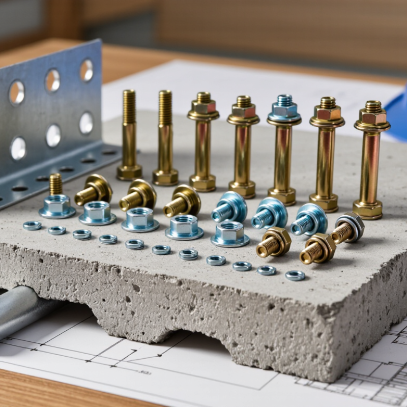
Solar footing expansion bolts secure metal brackets to cured concrete, transferring wind and uplift forces into the footing. They are not decorative fasteners. Their length must provide enough embedment without striking reinforcement or emerging beneath the concrete.
Common types include wedge anchors, sleeve anchors, and chemical anchors. Wedge anchors expand when the nut is tightened. Sleeve anchors use a surrounding sleeve and suit lighter structural demands. Chemical anchors bond a threaded rod inside a drilled hole, but require clean surfaces, correct curing time, and compatible materials.
Terminology matters: nominal diameter describes the bolt width, embedment depth describes the portion inside concrete, and fixture thickness includes the bracket and washers.
For many solar footings, installers begin by checking the engineering drawing rather than guessing from bolt diameter. A longer bolt is not automatically safer. Excess length can reduce thread engagement, interfere with the bracket, or reach unsuitable concrete zones.
Measure twice. Drill diameter, edge distance, concrete strength, and footing age all affect performance. In practice, the usable length often combines fixture thickness, washer and nut allowance, required embedment, and a small exposed-thread margin.
One detail deserves honest review: field measurements are sometimes less precise than drawings suggest. Dust-filled holes, uneven concrete, or an overlooked reinforcing bar can change the installation decision. Record the actual hole depth and tightening condition before loading the footing.
The best expansion bolt length depends on the footing, base plate, and required embedment. There is no universal size. Measure the steel base plate with a caliper, not by eye. Add the washer and nut thickness. Then add the minimum embedment specified for the anchor and concrete. The result is the minimum usable length.
For example, a 10 mm base plate, 6 mm washer, 12 mm nut, and 70 mm embedment require at least 98 mm of bolt length. Choose a slightly longer anchor if the design allows it. Leave enough thread for full nut engagement, but avoid excessive exposed thread. The hole must also be deeper than the embedment. Allow extra depth for dust and drilling tolerance. I once measured only the visible plate thickness. That small mistake could have caused poor engagement.
Mark the required depth on the drill bit with tape. Clean concrete dust from the hole before installing the anchor. Check the footing edge distance carefully. Expansion pressure near an edge can damage concrete. Confirm the anchor’s stated embedment, hole diameter, torque, and load capacity. Field conditions may differ from drawings. Recheck the actual footing before drilling. A longer bolt is not automatically safer. Overlooking concrete strength or spacing can weaken the connection.
The correct solar footing bolt length depends on more than the post diameter.
Soil strength, frost depth, uplift, shear, and bracket geometry all influence the required embedment. A longer bolt is not automatically safer.
ASCE 7-22 requires site-specific wind design, including exposure, height, and risk category. These inputs determine uplift forces at each footing. ACI 318-19 Chapter 17 also evaluates anchor breakout, pullout, steel strength, and edge distance.
In practice, I measure the assembled connection first. The bolt should extend through the washer and nut with visible thread engagement, while avoiding excessive projection that collects water or complicates maintenance.
Small details matter.
Very short bolts fail quickly. Sometimes.
NREL’s 2024 PV System Cost Benchmark placed utility-scale solar costs near 1.12 dollars per watt in its modeled 2023 baseline. That figure highlights a practical concern: foundation hardware must be reliable without becoming unnecessarily heavy or expensive. For many ground-mounted systems, engineers begin with soil testing, then calculate tensile demand before selecting bolt diameter and embedment. Frost-prone sites may need deeper foundations, while dense soils can reduce drilling difficulty but increase installation torque.
Field conditions often differ from drawings. That deserves attention.
A qualified structural engineer should verify the final length, corrosion allowance, washer size, and installation tolerance against the project’s stamped design.
Expansion bolt length depends on embedment depth, base-plate thickness, washers, and nut clearance. For a small solar footing with a 6–10 mm steel plate, 100 mm anchors are often practical. They usually provide about 70 mm of concrete embedment. Use 120 mm anchors for thicker plates or deeper embedment requirements. For a 150 mm concrete base, 120–140 mm anchors may offer better adjustment.
These are starting points, not universal specifications. ACI 318-19 requires engineers to check concrete breakout, pullout, edge distance, and cracked-concrete conditions. ICC-ES AC193 also emphasizes tested anchor performance under tension and shear. A 2024 NREL photovoltaic cost benchmark confirms that balance-of-system hardware remains a meaningful installation cost, so replacing undersized anchors later can become expensive.
On site, keep the anchor away from edges and reinforcement. A 12 mm bolt may need at least 80–100 mm embedment, but the approved anchor listing controls the final value. Expansion pressure can damage thin or weak concrete. Rooftop slabs require extra care around waterproofing and embedded steel. My practical mistake was treating a 100 mm anchor as automatically suitable for every 100 mm base; the plate and washer reduced its effective depth. Check the hole depth, clean dust thoroughly, and verify torque with a calibrated wrench. Wind design should follow ASCE 7-22, not guesswork.
2026 Best Expansion Bolt Length for Solar Footings?
Choosing an expansion bolt length for a solar footing starts with the base material, not the panel size. Concrete strength, footing thickness, edge distance, and bracket thickness all affect the calculation. The bolt must provide enough embedment after passing through the bracket, washer, and any leveling plate. A simple rule can mislead. Follow the anchor manufacturer’s tested embedment range and the project engineer’s specifications.
Clean the drilled hole carefully. Dust left inside can reduce expansion and create uneven holding power. Check the hole diameter, depth, and alignment with a calibrated gauge. The hole should be deeper than the required embedment, allowing space for drilling debris. Do not force a bolt into a shallow hole. That mistake is common. It can damage threads and leave the anchor under-embedded.
Tighten the nut with a calibrated torque wrench, using the specified torque rather than guesswork. Watch for concrete cracking, edge breakout, or a washer that no longer sits flat. Moisture exposure may require corrosion-resistant hardware and sealed interfaces. Inspect every footing after installation, then recheck accessible connections after severe wind or ground movement. Real sites are rarely perfect. If the concrete is weak, cracked, or thinner than drawings indicate, stop and request an engineering review before adding longer bolts. A longer anchor does not automatically create a stronger connection.
Practical sizing and installation reference for expansion anchors installed in sound, cracked or uncracked concrete. Dimensions are planning ranges, not a substitute for the selected anchor’s tested design data.
| Check or Dimension | Typical Planning Value | How to Select or Verify It | Why It Matters for Solar Footings | Site Acceptance Check |
|---|---|---|---|---|
| Common anchor diameter | M10 or M12 for light-to-moderate solar supports; M16 or larger where calculated loads require it | Select the diameter from the tension, shear, wind-uplift, overturning and seismic calculations. Do not choose by bolt length alone. | Larger diameters generally provide greater steel capacity, but concrete breakout and edge-distance limits may govern first. | Confirm the installed anchor, washer and nut match the approved structural design and anchor documentation. |
| Typical bolt length | M10: approximately 80–100 mm; M12: approximately 100–140 mm; M16: approximately 120–180 mm | Use: required length = fixture/base-plate thickness + washer and nut allowance + required effective embedment. | A longer bolt is not automatically stronger. Excessive length can create drilling conflicts or leave insufficient effective engagement. | Measure the actual base-plate thickness and compare the final embedment with the anchor’s published minimum and maximum values. |
| Effective embedment depth | Common planning range: about 8–12 times the anchor diameter; many M12 installations fall near 80–100 mm | Use only the effective embedment stated for the selected expansion anchor. The manufacturer’s tested value controls the design. | Embedment affects pull-out resistance, concrete breakout and resistance to wind-induced overturning. | Mark the drilling depth, verify the hole reaches it, and confirm the anchor is not stopped by reinforcement or debris. |
| Concrete thickness below anchor | At least the required embedment plus the anchor-specific clearance; avoid drilling through thin slabs | Check the footing or slab thickness from drawings or by approved investigation before drilling. | Insufficient thickness can cause breakout, blow-through, reduced capacity and damage to the underside of the footing. | Do not install when the available concrete thickness is less than the anchor approval or engineering requirement. |
| Minimum edge distance | Use the anchor-specific value; a preliminary layout often keeps anchors at least 6–10 diameters from an exposed edge | Calculate edge distance from the anchor centerline to the nearest concrete edge. Increase it when required for cracked concrete or high tension. | Anchors too close to an edge are more likely to cause concrete splitting or edge breakout. | Measure the base layout before drilling. Do not rely on the visible footing edge alone if concrete cover is uncertain. |
| Minimum anchor spacing | Use the tested spacing value; a preliminary layout often starts around 6–10 diameters between anchor centerlines | Check group-action reductions in the anchor design data, especially for closely spaced anchors carrying uplift. | Closely spaced anchors can share the same concrete failure cone and provide less capacity than isolated anchors. | Confirm center-to-center spacing with a template before drilling the second and subsequent holes. |
| Hole diameter | Use the exact drill diameter specified for the anchor; it is not interchangeable with the bolt diameter | For example, an M12 expansion anchor may require a different hole diameter than 12 mm. Follow the approved anchor data. | An oversized hole can prevent proper expansion; an undersized or damaged hole can prevent full insertion. | Use a calibrated bit, check wear, and reject holes that are visibly enlarged, oval, cracked or incorrectly positioned. |
| Hole depth | Drill to the specified minimum depth, commonly slightly deeper than the required embedment to allow dust clearance | Follow the anchor’s drilling-depth requirement and use a depth stop where possible. | A shallow hole prevents full embedment; a dirty or blind hole can leave the anchor above its intended position. | Check depth with a gauge or marked rod and remove all drilling dust before inserting the anchor. |
| Hole cleaning | Brush-and-blow cleaning according to the anchor instructions; repeat when the hole remains dusty | Use the specified brush size and air-cleaning sequence. Do not assume compressed air alone is adequate. | Dust reduces friction and can stop the expansion sleeve from gripping the concrete correctly. | The hole should be visibly free of loose dust, chips and standing water unless the anchor is specifically approved for that condition. |
| Concrete condition | Sound, adequately cured concrete with no delamination or major cracks at the anchor location | Use the design strength and cracked/uncracked-concrete category required by the project. Repair or relocate damaged areas. | Weak, cracked or poorly consolidated concrete can govern failure even when the steel bolt is adequate. | Inspect for cracks, honeycombing, spalling, moisture damage and corrosion of existing reinforcement before drilling. |
| Installation torque | Use the exact torque listed for the selected anchor; do not substitute a generic M10, M12 or M16 torque | Torque depends on anchor type, diameter, material, lubrication and approval. Apply it with a calibrated torque wrench. | Under-torquing may leave insufficient expansion; over-torquing can damage threads, crush concrete or compromise the anchor. | Record the torque, wrench identification and installation date for each footing or representative installation group. |
| Washer and base-plate fit | Washer should fully bear on the base plate without rocking, distortion or contact with weld irregularities | Verify washer outside diameter, thickness and grade against the structural design and anchor assembly. | Uneven bearing can introduce prying forces and reduce the reliable transfer of shear and uplift. | Check that the nut is fully engaged and that the exposed thread length is consistent after tightening. |
| Corrosion protection | Choose galvanized or stainless hardware according to the site’s moisture, salt, chemical and galvanic-corrosion exposure | Use a compatible complete assembly. Avoid mixing metals or coatings without checking galvanic compatibility. | Corrosion reduces cross-sectional area, weakens threads and can make future torque verification unreliable. | Inspect for damaged coating, rust staining, water traps and direct contact between incompatible metals. |
| Load-path verification | Check tension, shear, combined loading, concrete breakout, pull-out, pry-out and steel strength | Design for the governing wind uplift and overturning combination, including the solar array, support rail and footing geometry. | Anchor capacity must be adequate as a system; the strongest bolt cannot compensate for a weak footing or base plate. | Keep calculation records and verify anchor layout, footing dimensions and design loads before installation. |
| Post-installation inspection | 100% visual inspection plus documented torque checks and selected proof testing where required | Use the project specification or engineer-approved inspection plan. Proof tests must not exceed the approved test limits. | Early detection of incorrect depth, spacing, torque or damaged concrete prevents long-term movement and loosening. | Record location, anchor size, embedment, torque, concrete condition, installer and any corrective action. |
It secures a metal bracket to cured concrete.
Common types include wedge anchors, sleeve anchors, and chemical anchors.
Check the engineering drawing before choosing a length.
Embedment depth is the bolt length positioned inside the concrete.
Concrete strength, footing thickness, soil, frost, uplift, shear, and edge distance matter.
Confirm the hole location, diameter, depth, alignment, and edge distance.
Use a calibrated torque wrench and the specified torque.
Dust-filled holes can reduce expansion and create uneven holding power.
Stop if the concrete is weak, cracked, or thinner than shown.
Choosing the correct expansion bolt length is essential for creating secure, durable solar footings. The right fastener must provide enough embedment in sound concrete while allowing space for the mounting plate, washers, nuts, and any leveling components. To determine the required size, measure the total thickness of the base materials, add the necessary embedment depth, and account for site conditions such as concrete strength, edge distance, footing thickness, and expected wind or uplift loads. The key question is: What length of expansion bolt do I need for solar footings? The answer depends on the specific base design and engineering requirements rather than a single universal measurement.
For common solar bases, medium-length bolts may suit standard concrete pads, while thicker plates, raised supports, or deeper embedment requirements may call for longer options. Before final tightening, confirm the hole diameter, drilling depth, cleanliness, bolt alignment, and minimum edge clearance. Proper torque, full expansion, and a final stability inspection help ensure the footing remains strong and reliable over time.

Trope Solar